


Resources
- Description
- Warranty
- Shipping & Delivery
- Exchanges
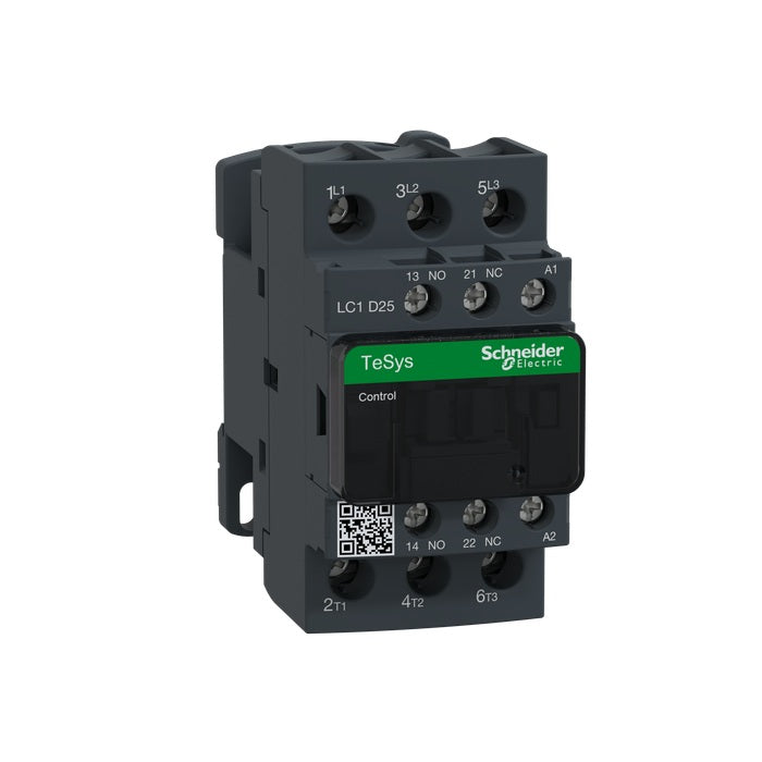
Schneider LC1D25G7 3NO IEC Contactor, TeSys Deca, 25A, 3 Phase, 120 VAC 50/60Hz Coil, Non-Reversing, Screw Clamp Terminals
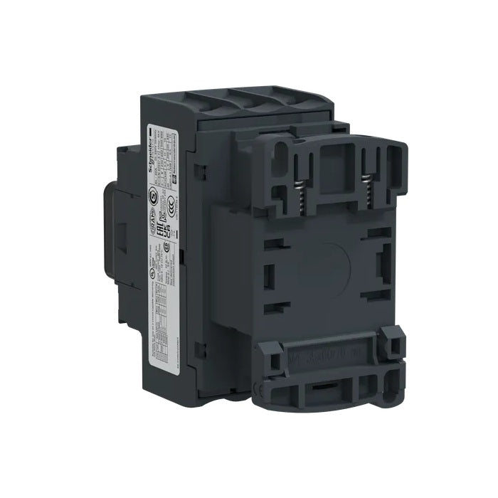
TeSys Deca contactor, 3 poles (3NO), for motor control applications up to 25A/690V AC-3/3e (11kW@400V). They can be used to create motor starters for almost any type of application. It provides a 120V 50/60Hz AC coil, 1NO+1NC built-in auxiliary contacts (NC mirror certified), connection by screw clamp terminals. For operating rates until 3600 cycles/hour and environments until 60°C, it procures high reliability and durability. Compact (45mm width), DIN-rail mounting or screw fixing. Contactor is rated for 7.5HP at 200-208VAC, 7.5HP at 240VAC, 15HP at 480VAC and 20HP at 600VAC three phase. Multi standards certified (IEC, UL, CSA, CCC, EAC, Marine). When used with a 480VAC up to 60A circuit breaker, this contactor can have a SCCR up to 85kA. When used with up to a 600VAC 60A Class J or CC fuse, this contactor can have a SCCR up to 100kA. Contactor is supplied with a 120 VAC 50/60 Hz coil. Contactor has one normally open and one normally closed auxiliary contact built-in as standard. The NC contact is mirror certified. Screw clamp terminals are used for load and auxiliary connections. An extensive line of accessories makes it easy to meet the requirements of most applications. The contactor is 3.35 inches tall, 1.77 inches wide and 3.62 inches deep. It weighs 0.82 lbs. Contactor is certified to UL, CSA, IEC, CCC, EAC and Marine standards.
Specifications
| MPN | LC1D25G7 |
| Range | TeSys Deca |
| Contactor Application | Motor control Resistive load |
| Utilization Category | AC-1 AC-4 AC-3 AC-3e |
| Poles Description | 3P |
| [Ue] Rated Operational Voltage | Power circuit <= 690 V AC 25...400 Hz Power circuit <= 300 V DC |
| [Ie] Rated Operational Current | 25 A (at <140 °F (60 °C)) at <= 440 V AC AC-3 for power circuit 40 A (at <140 °F (60 °C)) at <= 440 V AC AC-1 for power circuit 25 A (at <140 °F (60 °C)) at <= 440 V AC AC-3e for power circuit |
| [Uc] Control Circuit Voltage | 120 V AC 50/60 Hz |
| Motor Power kW | 5.5 kW at 220...230 V AC 50/60 Hz (AC-3) 11 kW at 380...400 V AC 50/60 Hz (AC-3) 11 kW at 415...440 V AC 50/60 Hz (AC-3) 15 kW at 500 V AC 50/60 Hz (AC-3) 15 kW at 660...690 V AC 50/60 Hz (AC-3) 5.5 kW at 400 V AC 50/60 Hz (AC-4) 5.5 kW at 220...230 V AC 50/60 Hz (AC-3e) 11 kW at 380...400 V AC 50/60 Hz (AC-3e) 11 kW at 415...440 V AC 50/60 Hz (AC-3e) 15 kW at 500 V AC 50/60 Hz (AC-3e) 15 kW at 660...690 V AC 50/60 Hz (AC-3e) |
| Maximum Horse Power Rating | 3 hp at 230/240 V AC 50/60 Hz for 1 phase motors 2 hp at 115 V AC 50/60 Hz for 1 phase motors 7.5 hp at 230/240 V AC 50/60 Hz for 3 phase motors 15 hp at 460/480 V AC 50/60 Hz for 3 phase motors 20 hp at 575/600 V AC 50/60 Hz for 3 phase motors 7.5 hp at 200/208 V AC 50/60 Hz for 3 phase motors |
| Compatibility Code | LC1D |
| Pole Contact Composition | 3 NO |
| Protective Cover | With |
| [Ith] Conventional Free Air Thermal Current | 10 A (at 140 °F (60 °C)) for signaling circuit 40 A (at 140 °F (60 °C)) for power circuit |
| Irms Rated Making Capacity | 140 A AC for signaling circuit conforming to IEC 60947-5-1 250 A DC for signaling circuit conforming to IEC 60947-5-1 450 A at 440 V for power circuit conforming to IEC 60947 |
| Rated Breaking Capacity | 450 A at 440 V for power circuit conforming to IEC 60947 |
| [Icw] Rated Short-time Withstand Current | 240 A 104 °F (40 °C) - 10 s for power circuit 380 A 104 °F (40 °C) - 1 s for power circuit 50 A 104 °F (40 °C) - 10 min for power circuit 120 A 104 °F (40 °C) - 1 min for power circuit 100 A - 1 s for signaling circuit 120 A - 500 ms for signaling circuit 140 A - 100 ms for signaling circuit |
| Associated Fuse Rating | 10 A gG for signaling circuit conforming to IEC 60947-5-1 63 A gG at <= 690 V coordination type 1 for power circuit 40 A gG at <= 690 V coordination type 2 for power circuit |
| Average Impedance | 2 mOhm - Ith 40 A 50 Hz for power circuit |
| Power Dissipation per Pole | 3.2 W AC-1 1.25 W AC-3 1.25 W AC-3e |
| [Ui] Rated Insulation Voltage | Power circuit 690 V IEC 60947-4-1 Power circuit 600 V CSA Power circuit 600 V UL Signaling circuit 690 V IEC 60947-1 Signaling circuit 600 V CSA Signaling circuit 600 V UL |
| Overvoltage Category | III |
| Pollution Degree | 3 |
| [Uimp] Rated Impulse Withstand Voltage | 6 kV IEC 60947 |
| Safety Reliability Level | B10d = 1369863 cycles contactor with nominal load EN/ISO 13849-1 B10d = 20000000 cycles contactor with mechanical load EN/ISO 13849-1 |
| Mechanical Durability | 15 Mcycles |
| Electrical Durability | 1.65 Mcycles 25 A AC-3 <= 440 V 1.4 Mcycles 40 A AC-1 <= 440 V 1.65 Mcycles 25 A AC-3e <= 440 V |
| Control Circuit Type | AC 50/60 Hz |
| Coil Technology | Without built-in suppressor module |
| Control Circuit Voltage Limits | 0.3...0.6 Uc (-40…158 °F (-40…70 °C)):drop-out AC 50/60 Hz 0.8...1.1 Uc (-40…140 °F (-40…60 °C)):operational AC 50 Hz 0.85...1.1 Uc (-40…140 °F (-40…60 °C)):operational AC 60 Hz 1...1.1 Uc (140…158 °F (60…70 °C)):operational AC 50/60 Hz |
| Inrush Power in VA | 70 VA 60 Hz cos phi 0.75 (at 68 °F (20 °C)) 70 VA 50 Hz cos phi 0.75 (at 68 °F (20 °C)) |
| Hold-in Power Consumption in VA | 7.5 VA 60 Hz cos phi 0.3 (at 68 °F (20 °C)) 7 VA 50 Hz cos phi 0.3 (at 68 °F (20 °C)) |
| Heat Dissipation | 2…3 W at 50/60 Hz |
| Operating Time | 12...22 ms closing 4...19 ms opening |
| Maximum Operating Rate | 3600 cyc/h at 60 °C |
| Connections - Terminals | Control circuit: screw clamp terminals 1 0.002…0.006 in² (1…4 mm²) - cable stiffness: flexible without cable end Control circuit: screw clamp terminals 2 0.002…0.006 in² (1…4 mm²) - cable stiffness: flexible without cable end Control circuit: screw clamp terminals 1 0.002…0.006 in² (1…4 mm²) - cable stiffness: flexible with cable end Control circuit: screw clamp terminals 2 0.002…0.004 in² (1…2.5 mm²) - cable stiffness: flexible with cable end Control circuit: screw clamp terminals 1 0.002…0.006 in² (1…4 mm²) - cable stiffness: solid without cable end Control circuit: screw clamp terminals 2 0.002…0.006 in² (1…4 mm²) - cable stiffness: solid without cable end Power circuit: screw clamp terminals 1 0.004…0.02 in² (2.5…10 mm²) - cable stiffness: flexible without cable end Power circuit: screw clamp terminals 2 0.004…0.02 in² (2.5…10 mm²) - cable stiffness: flexible without cable end Power circuit: screw clamp terminals 1 0.002…0.02 in² (1…10 mm²) - cable stiffness: flexible with cable end Power circuit: screw clamp terminals 2 0.002…0.009 in² (1.5…6 mm²) - cable stiffness: flexible with cable end Power circuit: screw clamp terminals 1 0.002…0.02 in² (1.5…10 mm²) - cable stiffness: solid without cable end Power circuit: screw clamp terminals 2 0.004…0.02 in² (2.5…10 mm²) - cable stiffness: solid without cable end |
| Tightening Torque | Control circuit 15.05 lbf.in (1.7 N.m) screw clamp terminals flat Ø 6 mm Control circuit 15.05 lbf.in (1.7 N.m) screw clamp terminals Philips No 2 Power circuit 22.1 lbf.in (2.5 N.m) screw clamp terminals flat Ø 6 mm Power circuit 22.1 lbf.in (2.5 N.m) screw clamp terminals Philips No 2 Control circuit 15.05 lbf.in (1.7 N.m) screw clamp terminals pozidriv No 2 Power circuit 22.1 lbf.in (2.5 N.m) screw clamp terminals pozidriv No 2 |
| Auxiliary Contact Composition | 1 NO + 1 NC |
| Auxiliary Contacts Type | Mechanically linked 1 NO + 1 NC IEC 60947-5-1 Mirror contact 1 NC IEC 60947-4-1 |
| Signaling Circuit Frequency | 25...400 Hz |
| Minimum Switching Voltage | 17 V for signaling circuit |
| Minimum Switching Current | 5 mA for signaling circuit |
| Insulation Resistance | > 10 MOhm for signaling circuit |
| Non-overlap Time | 1.5 ms on de-energization between NC and NO contact 1.5 ms on energization between NC and NO contact |
| Mounting Support | Plate Rail |
Standards
- CSA C22.2 No 14
- EN 60947-4-1
- EN 60947-5-1
- IEC 60947-4-1
- IEC 60947-5-1
- UL 60947-4-1
- IEC 60335-1:Clause 30.2
- IEC 60335-2-40:Annex JJ
- UL 60335-2-40:Annex JJ
- CSA C22.2 No 60947-4-1
Certifications
- UL
- CCC
- CSA
- Marine
- UKCA
- EAC
- CB Scheme
A. If not satisfied with a PRM product for any reason, customers should contact PRM. Returns submitted within 30 days of the original invoice and must be in original packaging and in new condition. Please contact PRM to provide additional information regarding a return.
B. PRM Limited Warranties are applicable to PRM branded products, non-transferable, and warrant against manufacturer defects in workmanship and materials under normal use for 1 year after the date of the PRM invoice unless otherwise stated. If PRM approves the product is accepted for return during the limited warranty period, PRM may repair, replace, or refund the amount paid by the customer.
C. Non-PRM branded products retain their manufacturer's warranty. Customer should contact the manufacturer for warranty service.
D. PRM is not liable for claims arising out of product misuse, improper product selection, improper installation, and/or product modification. PRM's liability in all events is limited to the purchase price paid for the product.
The vast majority of PRM products ship directly from our facility within one business day. High value items such as blowers, pumps, and fans may have extended lead times due to global supply. Please consider contacting PRM prior to your purchase if it's necessary to know an exact delivery date and time.
IMPORTANT: All goods must be inspected immediately upon delivery. Any shipping damage, missing items, or product defects must be reported to both PRM Filtration and the shipping carrier within 24 hours of delivery. Failure to report issues within this timeframe may result in your claim being denied. Please retain all original packaging materials, as they may be required for filing a damage claim.
Product Recovery Management, Inc. Returns/Exchanges
200 20th Street
Butner, North Carolina 27509.
Do not send us a damaged or defective item for exchange prior to contacting us. We will then contact you regarding your return. We cannot accept exchanges unless we have responded to your request.

